I just completed a stint of vacation relief as Third Assistant Engineer on the Texaco Minnesota (These experiences are described in Part I of this series). Texaco only operated two ships on the West Coast at the time, the Minnesota and Delaware, so jobs were rather limited. They needed a vacation relief for the 3rd Assistant Engineer on the Delaware, so I was offered an immediate reassignment. I was warned ahead of time that I might find the new ship a bit peculiar. Yet I was happy to take the assignment. I packed my bag and caught a flight from Los Angeles to Seattle. From there, I took a bus to Anacortes, Washington where I was to meet the ship. I arrived at the pier around 9PM.
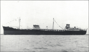
Texaco Delaware was not a T-2, but a close cousin. It nonetheless forms part of the story of my experiences in the Texaco fleet. It was probably the most unique steamship I ever set foot aboard. The ship was built alongside the Texaco Minnesota at Sun Shipbuilding in Chester, PA, and it entered service around the same time in 1943. It was similar in size to a T-2. But the lines were somewhat different. A prominent feature was a very fat stack located at the forward end of the deckhouse, rather than aft on a T-2.
Texaco operated five ships of this type in 1961. They were not a standard Maritime Commission design. They were specially designed for Texaco with the idea in mind of outrunning submarines. The ships were slightly smaller than a T-2 and had a lower cargo capacity. The power plant was geared turbine, with a maximum rating of 10,500 SHP. This gave the ship a service speed of 16 knots. But in a lightly loaded condition the ship was known to make speeds upwards of 18 or 20 knots.The ship’s listed homeport was Wilmington, California. It actually spent most of the time in the Pacific Northwest, carrying petroleum products of all types to different ports in the Puget Sound area. We made two trips to Portland, Oregon and one to Los Angeles each month. At least 50% of our time was spent in restricted waters.
LEARNING THE HARD WAY
I learned my lesson aboard Minnesota the hard way. After reporting aboard, I joined the Second Assistant Engineer on the mid watch for a tour of the engine room. Compared to a T-2, the machinery spaces were relatively compact. There were a lot of strange features.
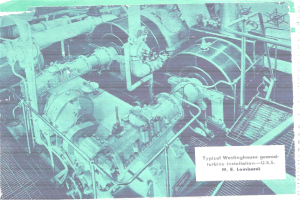
The engine was a conventional cross compound Westinghouse geared turbine. The double reduction gears were of the nested type. It was a fairly neat installation. The gears were very noisy in operation compared to those aboard a naval vessel. Control was by a set of fairly conventional throttle wheels located on the main gage board at the front of the engine. The engine room looked basically the same, as shown in the following illustration:
 The fire room was immediately forward of the engine room on the upper level. It was accessible through a watertight door to the left of the throttle platform. The first unusual feature was the boilers themselves. There were two Foster-Wheeler “M” type boilers located side by side. The boilers were divided furnace with controlled superheat. They produced steam at approximately 450 psi and 740ºF. There were three burners in the saturated side and two in the superheater furnace. The boilers were basically scaled down versions of those found on most naval surface combatants of that era. Boilers of this type, however, were very rarely found aboard commercial ships. They took up less space than the sectional header boilers on a T-2 tanker and were more responsive to changes in steam demand. Boiler control was done by a Bailey pneumatic system similar to the one on a T-2, except that there were steam temperature and pressure controllers on the panel. During maneuvering and port operations, it was our practice to keep one burner in use in the superheater furnace with the temperature controller at its minimum setting of approximately 630°F. Operation of the boilers could be a bit confusing to someone who had never seen them before.
When you got away from the firing aisle, the fire room was quite dark. It seemed like everything was covered in a layer of soot. I never dared go all the way to the top of the space because of the many uptake and casing leaks. When you blew tubes, it seemed like soot flew around everywhere. It was necessary for everyone in the fire room to wear goggles.
The cargo pumps were steam turbine driven. They were located in a amidships pump room. There was no automatic dump valve to the main condenser. The auxiliary exhaust valve located on the throttle platform had to be manually regulated to maintain an operating pressure of about 7 to 10 psi in the cargo pump exhaust line. It could not be left unattended without risking the loss of vacuum in the main condenser.
While we continued our tour of the lower level, the Second Assistant made a point to show me how to inject sawdust into the seawater circulating side of the main condenser. I wondered about this. I would find out why later on.
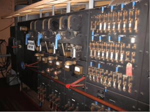
The electrical installation was straight out of the early century. It was 230 volts DC. There were two 250 kW turbo generator sets located on the starboard engine room on the upper level. The generators were of open construction with commutator, brushes, and windings completely exposed. They accumulated a lot of carbon dust during operation, so each set had to be cleaned once a month.
The main switchboard was of the live front type with all bus bars, fuses, and circuit breakers completely exposed. All that separated you from electrical shock was a small wooden handrail. It was of similar construction to the main switchboard on a Liberty Ship, shown in the following illustration:
The ship’s lighting system was supplied from a pair of 25 kW 230/115 VDC motor generator sets. Because of their limited capacity, the Chief Engineer was instructed to only use 25-watt bulbs around the ship. The combination of mahogany lined passageways and 25-watt bulbs resulted in an atmosphere akin to a 1910 ocean liner.It was the practice aboard Texaco tankers to assign a full time electrician to T-2 tankers with AC distribution systems. On gear driven ships like the Texaco Delaware, this duty was assigned to the Third Assistant Engineer. Therefore, I doubled as the only electrician. This policy made no sense to me. DC machinery requires more maintenance than AC machinery because of the presence of commutators and carbon brushes. I found many of the ship’s motors caked with carbon dust and controllers with dirt and lube oil inside. The first time I took Megohmmeter (Megger) readings, I found around 5 motors with zero grounds. For some reason, the main circulating pump and LP air compressor motors were mounted with the rotors athwart ships. It was very difficult to keep brushes in them. With the exception of the main feed pumps, cargo pumps, steering gear, and major deck machinery, most of the auxiliary machinery was electric motor driven.
I had the same duties I had aboard Texaco Minnesota for the periodic cleaning of the main lube oil purifiers and strainers and maintaining lube oil levels in all equipment. This made for a very full plate. I looked on this as an excellent opportunity to learn something. I figured that I could not mess up the electrical plant any more than it was already. Armed with my Megger, some rags, cleaning solvent, and a copy of the Navy EM 1&C training manual, I undertook its cleaning. I also enjoyed the fact that I could collect overtime for going around the ship and changing light bulbs. I had a locker that contained a supply of light bulbs and brushes.
The ship’s refrigeration plants were in a compartment in the after part of the engine room. The machines were of the ammonia type. Ammonia is of course poisonous. One day, after the First Engineer had changed over machines, the entire engine room stank like a baby’s diaper for several hours afterwards.
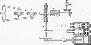
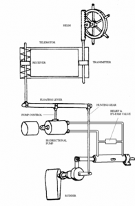
Last but certainly not least was the steering gear. I have never seen another like it. It was of the steam screw type, about 20 feet in length. A small, two-cylinder steam engine drove a right and left hand screw shaft through a set of spur gears. The screw shafts ran through a pair of large nuts that were connected through link arms to the tiller head. Rotation of the screw shafts caused one nut to be screwed forward and the other aft. This action caused the rudder to be turned. Remote bridge control was by hydraulic telemotor. You could hear a rattling noise from the steering gear all over the after part of the ship whenever the rudder was put over.
Our procedure for getting underway was a lot less formal than it was aboard a naval vessel. On the turboelectric T-2s, we started answering bells as soon as STANDBY was received on the telegraph with no testing whatsoever. There was a little more to it on the Delaware. Prior to assuming the watch, I would venture out to the cargo deck to check the sailing time posted on the blackboard at the gangway. Underway preps required about 45 minutes.The first step was to start up the standby generator. Two persons were required for this operation. The oiler would go below to open the exhaust valve, line up the auxiliary circulating and condensate pumps, and then come up to operate the hand lube oil pump while the engineer started up the unit. DC generators do not require synchronization, so all that was necessary was bringing the oncoming unit up to bus voltage. One of the generators was replaced at some time in the ship’s life due to damage from excessive water slugs in the turbine, so the two sets aboard Delaware were of different models and the startup procedures were somewhat different.
My next step was to go up on deck and look over the stern. If there were any small boats in the area near the propeller, I would shoo them away. I was the only engineer on the ship that did this, but it was what I was taught at MMA.
I would then stick my head out into the fire room and tell the fireman I was going to put steam on the engine. The oiler would go up to open the bulkhead stop valves while I disengaged the jacking gear. That usually required the use of a pipe wrench on the motor shaft to release the torque.
I went back to start spinning the engine. The procedure was to first go astern and then back and forth until the main steam line temperature was up, finally leaving the engine to turn over slowly ahead at about 3 to 5 RPM.
About then, the whistle would blow overhead. It was time to go and test the steering gear. The first step was to take a swab and smear lube oil over every moving part in sight. It was necessary to then crack the steam valve slightly with the cylinder drains open to work out the water. The final step was to engage the telemotor by dropping a large pin into place and report to the mate that the gear was ready for testing. He would then cycle the rudder to hard over. It was a bit of a scary sight with lots of clattering and banging and parts flying around.
It was then time to test the EOT. Nothing on this ship was simple. The telegraph was operated from the bridge by about 300 feet of bicycle chains. To get it to ring, you had to swing it all the way to the FULL position and back again, like you saw in the movie Titanic. This took a considerable amount of effort. Complicating things was the fact that the chains would stretch or go slack, depending on the loading condition. Sometimes, the engine room pointer would wind up on the line between the SLOW and HALF positions. This required calling up the bridge to find out what the bell was.
The throttles themselves were easy to operate. Because of the noisy reduction gears, you could always tell when the shaft started to rotate without needing to look at a mirror. One significant difference from U.S. Navy procedures was that we treated every STOP bell as a stop shaft bell by the use of astern or ahead steam, as appropriate.
On the first FULL bell, the salinity indicator would frequently peg out accompanied by an audible alarm. The procedure was to turn the throttle over to the oiler and run down to the lower level. Next to the main circulating pump was an eductor arrangement with a funnel on the suction side that discharged into the condenser circulating water inlet piping. It was necessary to align the eductor and pour a bag of sawdust into the funnel until you heard the salinity alarm stop ringing. Sometimes, more than one bag would be required. The idea was that particles of sawdust would be drawn into tube leaks by the condenser vacuum, swell, and plug the leak. It was an old engineer’s trick that actually worked for short periods. We never could get the Chief Engineer to properly shut the plant down and fix the leaking tubes because of the requirement to handle the main cargo pump exhaust when in port.
Once during a tour of a shore side generating plant, I discovered a similar arrangement for sawdust injection in order to avoid the shut down of a large generator with disruption to the electrical distribution system
One time when we were in port, the salinity alarm went off and would not stop. I finally gave up after pouring five bags of sawdust and went up to see the Chief Engineer. This chief was not one to get involved in the day-to-day operations of the plant. But he had a remedy for me. He proceeded to the galley and got me a can of oatmeal. It worked.
By now, I knew that the boilers had to be hopelessly salted up. Both the First and Second Assistant Engineers were off the ship, so it was up to me. I proceeded up to the boiler chemistry sink in the fire room, picked up the Bull & Roberts manual, and proceeded to teach myself how to test water. I finally figured out how to test for salinity. Naturally, the readings were way up there. I traced out the chemical injection system and figured out how to inject chemicals. Naturally, this took a few hours. From there, I decided that I better give the boilers a bottom blow. I had to ask the fireman where the valves were. They turned out to be in back of the boilers down in the bilges. I had the fireman raise the water level and went back behind the boilers. There were no lights and it was pitch-black back there. I had to hunt for the valves with my flashlight. When I opened them, everything started rumbling and soot flew all over the place. I admit to being a bit scared. Fortunately, the First Assistant arrived back on board in time to bail me out.
Another incident that I remember occurred while we were transiting the Columbia River. All four main turbine glands started throwing copious sprays of water into the engine room. We had panic buttons at the throttle board so we could call other engineers for help when required. I pushed all of them with no result. They were all up in the forward deckhouse playing cards. I decided that the problem had to be drains backing up from the gland exhauster. I went down to check the LP drain tank. It was an oddball arrangement with a horizontal centrifugal pump located on top of the tank. I tried shifting to vacuum drag. But that just caused a loss of vacuum in the condenser. The pump was still running, but it had lost suction. I had a bright idea. I told my oiler to get some rags, wrap them around the pump casing, and start pouring cold water on it. He looked at me like I was nuts, but did as I suggested. Darned if it didn’t work. He was quite impressed.
I am sure the question is arising in one’s mind: “Wasn’t it awful to have to sail on such a rust bucket? The answer is on the contrary. I enjoyed this tour more than either of the other Texaco ships that I served aboard. I learned an awful lot in a very short time. It was a great training experience, and I found it very useful during my subsequent naval career. I was sorry to leave when the time came. Texaco Delaware was scrapped in 1970.
You can still find devices such as a steam steering gear, hydraulic telemotor, and bicycle chain operated EOT aboard the Liberty Ship SS John Brown, which runs periodic daytime cruises out of Baltimore, Md.
By now, I had worked six months and accumulated 3 months’ vacation. Since Texaco only operated two ships on the West Coast, I was told that I would probably have to go to the Gulf if I wanted to stay with the company. They operated 23 ships out of Port Arthur at the time.
There is still one more ship to discuss in this series. It was a bit more conventional than the Texaco Delaware. But, there are plenty more adventures to talk about.
George W. Stewart is a retired US Navy Captain. He is a 1956 graduate of the Massachusetts Maritime Academy. During his 30 year naval career, he held two ship commands and served a total of 8 years on naval material inspection boards, during which he conducted trials and inspections aboard over 200 naval vessels. Since his retirement from active naval service in 1986 he has been employed in the ship design industry where he has specialized in the development of concept designs of propulsion and powering systems, some of which have entered active service. He currently holds the title of Chief Marine Engineer at Marine Design Dynamics.

Pingback: Shipping Out: My Experiences on a Commercial Tanker (Part III) | Naval Historical Foundation
George Fleming